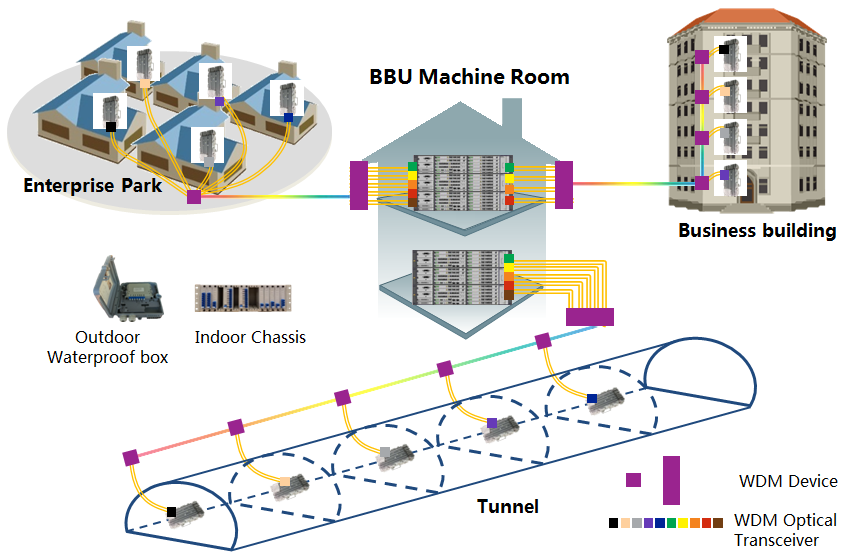
With the increase of city high-rise buildings, underground rail transportation, office parks, business buildings in recent years, indoor network distribution become the new competition field for carriers. There are more data traffic, more client access such as mobile phone and other terminals in indoor networks. At same time, many indoor space separation degrades the signal coverage of a single RRU or AP. So more RRU or AP are deployed with higher density and lead to higher requirement for fiber cable resources density in indoor distribution system.
Indoor distribution system has dense fiber cables. Many new fiber cables are required if adopting one-to-one fiber connection mode, which is costly;
♢ Laying new fiber cables needs a long time to coordinate with the property management or municipal d control, which directly prolongs the construction period;
♢ Most of the new business buildings have pre-layed fiber cables in construction process. buying or hiring the pre-layed fiber cable is costly.
Therefore, the utilization of fiber cables becomes the main constraint factor of the CAPEX and the construction cycle in indoor distribution field.
Summary
Indoor distribution systems have different scenes, various requirements, and high bandwidth. In addition to maximizing the utilization of optical fiber, the fiber capacity expansion solution for indoor distribution system usually should fulfill the following requirements:
1. Multiple-scene solutions for different BTS conditions;
2. Fast installation in different scenarios;
3. Future expansion possibility

Introduction
According to the characteristics of indoor distribution, three typical scenes are introduced to describe the optical fiber expansion in indoor distribution system.
1. Enterprise Park
WDM equipment (active or passive) is placed in the park and the BBU room, multiple fiber cables of several buildings in the park are converged into the 1~2 fibers cable and transmitted to BBU.
2. Business Building
WDM equipment (OADM) is placed in every 1 or 2 layer of the business building. Via OADM, 18 RRU can use only 2 fibers in the building shaft to build a linear network and cover the whole building.
3. Tunnel
WDM equipment (OADM) is placed in every service node of a tunnel. Via OADM, multiple modes can use only 2 fibers to build a linear network and cover the whole tunnel.
Features
◇ Flexible
♢ Multiple topologies such as linear, dual-star, etc.
♢ Multiple indoor distribution scenarios such as enterprise park, business building, etc.
♢ Support harsh outdoor environment (IP66, -40~85℃)
◇ Reliable
♢ Pure passive optical device, Low failure rate;
♢ Active optical device is manageable, optical link status is monitored, 1+1 or 1:1 protection for trunk fiber link;
♢ Support CPRI data rate (9.8G/6.14G/4.9G/2.45G/1.22G) in one platform
◇ Saving
♢ OADM solution with low insertion loss;
♢ 1~2 fibers for optical trunk link, high fiber utilization
Product List
|
Product |
Description |
|
OTP5500 |
Active WDM platform, 19” 1U/2U/5U chassis, CWDM MUX, OADM, OEO and OLP cards, outdoor type is optional |
|
OTP5300 |
Passive CWDM MUX, 4/8/12/16/18 channels, Optional single or dual core for trunk optical link, available for the installation in cabinet, outdoor pole/wall mounting waterproof boxes |
|
CWDM Optical Transceiver |
Wavelength range 1271nm~1611nm, 155M/622M/1.25G/2.5G/10G optional, up to 120km transmission distance |